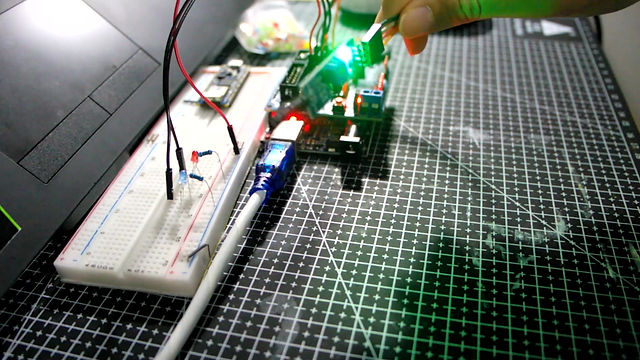
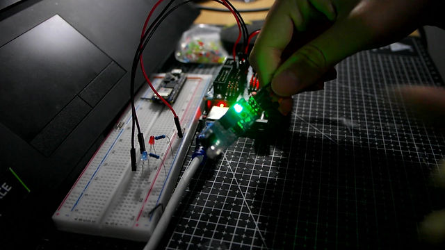
"Much of the technical work of physical computing is about figuring out what forms of energy a person is generating, and what kind of transducer you can buy or build to read that energy. "
---Electricity: the Basics
Course Content: Arduino, electric circuit, sensors, etc.
Time: 2020/09/02 - 2020/12/09
Instructor: Yeseul Song
Rain Sensor

Coding:
https://create.arduino.cc/editor/lea_1998/594be563-8ec1-44a8-a2fa-64fc95612199/preview
Sensor test data:
No water: 1023
Have a few drops: 500-700
Pour water:200-300
- What does the sensor do?
The rain sensor can detect whether there is water/rain on the copper tracks and the amount of water/rain.
- How does the sensor work?

"The input to the inverting terminal is set to a certain value by varying the potentiometer and the sensitivity is set. When the rain board module’s surface is exposed to rainwater, the surface of the rainboard module will be wet, and it offers minimum resistance to the supply voltage. Due to this, the minimum voltage will be appearing at the non-inverting terminal of LM393 Op-Amp. The comparator compares both inverting and non-inverting terminal voltages. If the condition falls under case(1), the output of the Op-Amp will be digital LOW. If the condition falls under case(2), the output of the Op-Amp will be digital HIGH. The below diagram shows the equivalent circuit of both the conditions."
Reference: https://components101.com/sensors/rain-drop-sensor-module
- Application, ideas, experience?
- Automatic windshield wipers
- Smart Agriculture
- Home-Automation
Vibration Sensor

- What does the sensor do?
The rain sensor can detect whether the sensor is shaken and the amplitude of the vibration.
- How does the sensor work?
"LM393 Comparator IC is used as a voltage comparator in this vibration sensor module. Pin 2 of LM393 is connected to Preset (10KΩ Pot) while pin 3 is connected to the vibration sensor. The comparator IC will compare the threshold voltage set using the preset (pin2) and the Vibration Sensor pin (pin3)."
Reference: https://components101.com/sensors/sw-420-vibration-sensor-module
- Application, ideas, experience?
-Shocks triggering
-Smart car
-Earthquake alarm

Simulated Kitchen - Project idea
A cooking game. With a simple interface (Basically made of cubes),players can explore interactive behaviors (beating, pouring water, etc.) by themselves, the installation will make different cooking sounds. Through the correct sequence of interactive actions, they will finally cook a dish.
I think the interested part of the installation is the transformation from the interactive behaviors to cooking result and the contrast between simple interface and the complexity of the real kitchen.
Infrared Obstacle Detector(Photoelectric button)

- What does the sensor do?
The sensor can detect whether there are obstacles within a distance of 1-3 cm.
- How does the sensor work?
This sensor has two main components: IR LED Transmitter and photodiode Receiver. The LED will emit IR light,which is invisible to us as its wavelength (700nm – 1mm) is much higher than the visible light range. If there is obstacles, the IR light will reflect from the surface, and the photodiode receiver will detect the reflected light, and feedback the data to the micro-controller.
Reference: https://components101.com/sensors/ir-sensor-module
- Application, ideas, experience?
I have used this sensor as a turntable counter, the structure is below:


Every time the turntable rotates, the wooden stick will be detected by the sensor as an obstacle, and the number of laps will be accumulated once.
Rotary Encoder (*Problems)


In console log, the direction of the encoder always changes, so two LED blinking constantly.
I'm not sure how to connect the pin of the sensor, and whether to add resistors or capacitors.
Serial output to p5.js
I used one of my ICM projects "rain", and tried to manipulate it with a button, a potentiometer and a rain sensor.
Original Code: https://editor.p5js.org/Lea-0821/sketches/x7mOLX6KL
- About p5.Js "Rain" project
The original project constrain the number of rains, the number is 15. The direction of the rain is following the mouse position, and the position of the rains are random.
- How the Arduino communicate with p5.js?
There are 2 ways to communicate with p5.js:
-
Binary
Using Serial.write(Arduino) & serial.read(p5.js):
Serial.write send the binary code
serial.read read the binary code and translate the code according to ASCII
-
only 1bate
-
0-255
-
ASCII
Using Serial.print(Arduino) & serial.readLine()/ serial.readString()(p5.js) & String:
Serial.print send the ASCII number
serial.readLine read the text as string until it read a new line
In this project,I use the second way.
The button control the start of rain. If rain sensor detect water, the amount of rains will increase, the defalut number is 5, the maximum number is 20. The potentiometer control the angle of the rain.
Arduino code: https://create.arduino.cc/editor/lea_1998/801af8a0-3010-4fef-b36b-e5b5f2c2d203/preview
P5.js code: https://editor.p5js.org/Lea-0821/sketches/JwKr7RYKm
Serial input from p5.js
In this case, I use 6 LEDs as output, arranging them in circle. As for the p5.js, the coordinates of the mouse are converted into angles corresponding to the positions of the LEDs.
Original Code: https://editor.p5js.org/Lea-0821/sketches/x7mOLX6KL
- How the p5.js communicate with Arduino?
Using Serial.read()(Arduino) & serial.write(p5.js)
serial.write():
If gave it a variable or literal and that’s numeric data, it will send it as raw binary value.
e.g.(p5.js)
function mouseDragged(){
outByte = int(map(mouseY,0,height,0,255))
}
If you give it a string, it will send out that ASCII string.
e.g.(P5.js)
serial.write(outByte+’\n’);
Arduino to encode ASCII string:
e.g.
void setup(){
Serial.begin(9600);
Serial.setTimeout(10); //set the timeout for parseInt
}
void loop(){
if(Serial.available()>0){
int inByte = Serial.parseInt();
if(inByte>=0){ // = 0 because parseInt return 0 if timeout or string is legitimately 0
Serial.write(inByte);
analogWrite(5,inByte);
}
}
}
Arduino code: https://create.arduino.cc/editor/lea_1998/dd817108-3db5-4930-9565-19ca6088ca13/preview
P5.js code: https://editor.p5js.org/Lea-0821/sketches/4wVvzUS4_
- Problems & Solution
Because I only use the varible in p5.js and deliver the number to the Arduino serial, I have to use 2 map(one in p5.js to convert angle from 360 to 255; one in Arduino to convert number from 255 to 360), or for the degree above 255 in p5.js, the led won't turn on.
SPI
All SPI devices have a common set of connections:
-
a Serial Data In (SDI) connection, on which the controller sends data to the peripheral devices.
-
a Serial Data Out (SDO) connection, on which the peripheral devices send data to the controller.
-
a Serial Clock (SCLK) connection, on which the controller sends a regular clock signal to the peripheral devices.
-
one or more Chip Select (CS) connections, which the controller uses to signal the peripheral devices when to listen to incoming data and when to ignore it.
SCK: Synchronous sensors don’t have their own clock, and they hook up with the microcontroller’s synchronous serial protocols, which could supply the clock signal.
Bus protocols:All peripherals share the same data lines (master in/out & slave in/out), the clock and chip select pin will help the microcontroller to tell each chips whether to listen or not.
4 wires:
-
controller -> peripheral (MOSI)
-
peripheral -> controller (MISO)
-
clock
-
chip select
First three lines can be shared.
SD card
Initialize the Card
Reference Code: https://www.basemu.com/how-to-use-an-sd-card-with-arduino.html

Write sensor data
Reference Code: https://www.basemu.com/how-to-use-an-sd-card-with-arduino.html
- while(1)?
Endless loop, to let the program no longer execute

Problems:
1. Play music with SD card

The biggest problem is speaker can not play the audio with clear vioce. I have a hard time identifying the melody in the noise. I think the reason may be the absence of chip LM386 and capacity, whose function is amplifying the sound and reducing the noise.
I will try this again once I get LM386.
2. A bug(?)
While I trying the SD card sensor, the Arduino IDM sometimes report the error that cannot update the program to the microcontroller, the error info is :
avrdude: stk500_recv(): programmer is not responding
avrdude: stk500_getsync() attempt 1 of 10: not in sync: resp=0x28
avrdude: stk500_recv(): programmer is not responding
avrdude: stk500_getsync() attempt 2 of 10: not in sync: resp=0x28
avrdude: stk500_recv(): programmer is not responding
avrdude: stk500_getsync() attempt 3 of 10: not in sync: resp=0x28
avrdude: stk500_recv(): programmer is not responding
avrdude: stk500_getsync() attempt 4 of 10: not in sync: resp=0x28
avrdude: stk500_recv(): programmer is not responding
avrdude: stk500_getsync() attempt 5 of 10: not in sync: resp=0x28
avrdude: stk500_recv(): programmer is not responding
avrdude: stk500_getsync() attempt 6 of 10: not in sync: resp=0x28
avrdude: stk500_recv(): programmer is not responding
avrdude: stk500_getsync() attempt 7 of 10: not in sync: resp=0x28
avrdude: stk500_recv(): programmer is not responding
avrdude: stk500_getsync() attempt 8 of 10: not in sync: resp=0x28
avrdude: stk500_recv(): programmer is not responding
avrdude: stk500_getsync() attempt 9 of 10: not in sync: resp=0x28
avrdude: stk500_recv(): programmer is not responding
avrdude: stk500_getsync() attempt 10 of 10: not in sync: resp=0x28
I found the reason and the solution on stack overflow:

When I take off the SD card sensor, the prgram can be uploaded. Is that bug can be fixed or what is the reason of that?
Stack overflow link:https://stackoverflow.com/questions/37377999/cant-upload-to-arduino-uno-board-error-message-avrdude-stk500-recv-progr
I2C
Connect two chips together with 2 wires:
-
Data line: send the address of the device you want to speak, the device will speak back. (The controller will change the pin from being an output to input)
-
clock
#Interrupt
https://www.youtube.com/watch?v=QtyOiTw0oQc
#millis()
What the difference?
APDS-9960
1. Color
The problem is the color is not so accurate. It is related with the distence.

2. Gesture
The problem is the sensor is working, but it cannot detect the gesture.
